Mid-Power HF Amplifiers
Updated 20190906
New thoughts on HF amplifiers
When out on mobile radio trips I dream about a big signal to shout back at the DX I can hear (SSB). My Elecraft KXPA100 is wasteful, like all class-AB designs. It also needs a healthy 13V+ supply to get a full 100W output, whereas a good car battery drops to <12.5V when off charge. Some amateur class-AB amplifiers are still in the 1980s with obsolete IRF510 or Motorola RF parts.
This page looks at two designs of HF amplifier for mobile/portable operation. A new concept and an updated class-AB.
New Concept HF Amplifier (2018-)
Here’s a simulated frequency spectrum in LTSPICE XVII with 3kHz modulation. Peak power 75W from a 13.8V power supply.
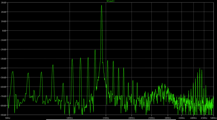
Though the result looks spiky, the spurious is <50dBc which is the required limit for ham radio equipment. This is only an AM modulated test, the next plot shows a 2-tone test (SSB) signal simulated in LTSPICE. The frequency is 14.2MHz.
The FFT resolution is not great, but does show the two peaks and an acceptable level of spurious. The 2-tone waveforms in the time domain also show quite faithful reproduction between the input and output. I know how annoying the splatter is on 20m, don’t want to make it worse!
This is the first test PCB, which didn’t work well but led the way to correct many problems!
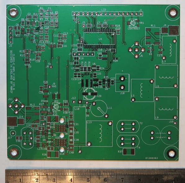
Initial tests confirm high efficiency from the power stage, with 65W produced from 13.8V, 5.3A = 93%. Modulating this raw power while keeping safety margins on the FETs is a difficult challenge. I am designing a new board to overcome the many problems of the first one.
Much of the technology is new or not widely given in books anywhere. I found some approaches to circuit design which may overcome the failure of previous experimenters with this type of amplifier. As said above, I’m designing a battery powered amplifier in the 100W class for field trips. There’s little point in having a fixed station amplifier with mains power, because the efficiency and size saved by switching type amplifiers is not really needed. A mobile amplifier with 100W+ powered from an easily available battery would be a more valuable invention.
The bands above 20MHz will remain closed for many years to come. The only viable bands for mobile SSB operation are then 80m,40m,20m,17m. So, I’m designing for this frequency range which makes thing easier.
If anyone would like to collaborate on this project I can share far more information privately than given here? Unlike the class-AB projects the high efficiency work is closed source, and no further details can be shared.
Realisable Efficiency
A practical amplifier needs a drive source, transformers, filters, ancillary circuits. All consume power, perhaps from a battery. Let’s look at power loss in a typical class-AB amplifier in terms of dB and percentage
So for 100W, dc input power will be over 250W and a 12V amplifier takes 20A of current. For lower power outputs efficiency drops substantially, down to perhaps 30%. SSB duty cycle is generally only 25%, so amplifier efficiency will be way below 60%.
It’s tempting to think envelope restoration and digital amplifiers provide >90% efficiency. With a high efficiency power stage, other losses become important. A 25% loss (dB) in an output transformer knocks efficiency down to 75%. Designing a system with combined efficiency above 75% maybe impossible given the constraints of these passive circuit elements.
For the example of a 100W amplifier, it will pull 133W, or 10A from a 13.3V power supply. It’s better than class-AB, but there will always be substantial wastage. Wastage is dependant on the power loss of every power handling component in the system. A zero-ohm impedance transmitter stage is not realisable.
100W Class-AB (2018-)
The new MRF101 LDMOS from NXP provide many advantages over the Mitsubishi RDxx series found in most HF power amplifiers.
One major disadvantage - they need at least 25V to operate properly. As concluded from previous work, it’s practically impossible to persuade DMOS switching FETs to give reliable 1-30MHz RF output. With the MRF101 easily available at about 10x the cost of DMOS FETs but half the price of the RD100xxx devices, they look a superior solution.
A lot of ground-work was already done here in terms of auto-band switching; SWR protection and monitoring; boost power supply; Low pass filters; output transformers, it was decided to have a last push and productionise the best technology and combine with the latest FETs. This project should provide a minimal parts count 100W (PEP) amplifier which has several advantages over products like the Elecraft KXPA-100.
A prototype PCB and 160x100mm enclosure are near completion as shown here.

As with previous HF amplifier projects, the hardware is open source and the software is closed source. I refuse to get any of my designs easily ripped off by Chinese manufacturers. As of late 2019, there is much work to do on the software, but the circuit diagram and Gerber files are available from these links.
Amplifier
Micro+filters
Gerbers.zip
The amplifier needs 27V power supply, which can be made by “600W” boost modules available on eBay. Search for “600W boost converter” on eBay or Amazon.
The software is written in Code Composer Studio (CCS) for an MSP430G2553 target. The items list (BOM) will follow when the software is more complete and the design more proven.
Updated 20190906
New thoughts on HF amplifiers
When out on mobile radio trips I dream about a big signal to shout back at the DX I can hear (SSB). My Elecraft KXPA100 is wasteful, like all class-AB designs. It also needs a healthy 13V+ supply to get a full 100W output, whereas a good car battery drops to <12.5V when off charge. Some amateur class-AB amplifiers are still in the 1980s with obsolete IRF510 or Motorola RF parts.
This page looks at two designs of HF amplifier for mobile/portable operation. A new concept and an updated class-AB.
New Concept HF Amplifier (2018-)
Here’s a simulated frequency spectrum in LTSPICE XVII with 3kHz modulation. Peak power 75W from a 13.8V power supply.
Though the result looks spiky, the spurious is <50dBc which is the required limit for ham radio equipment. This is only an AM modulated test, the next plot shows a 2-tone test (SSB) signal simulated in LTSPICE. The frequency is 14.2MHz.
The FFT resolution is not great, but does show the two peaks and an acceptable level of spurious. The 2-tone waveforms in the time domain also show quite faithful reproduction between the input and output. I know how annoying the splatter is on 20m, don’t want to make it worse!
This is the first test PCB, which didn’t work well but led the way to correct many problems!
Initial tests confirm high efficiency from the power stage, with 65W produced from 13.8V, 5.3A = 93%. Modulating this raw power while keeping safety margins on the FETs is a difficult challenge. I am designing a new board to overcome the many problems of the first one.
Much of the technology is new or not widely given in books anywhere. I found some approaches to circuit design which may overcome the failure of previous experimenters with this type of amplifier. As said above, I’m designing a battery powered amplifier in the 100W class for field trips. There’s little point in having a fixed station amplifier with mains power, because the efficiency and size saved by switching type amplifiers is not really needed. A mobile amplifier with 100W+ powered from an easily available battery would be a more valuable invention.
The bands above 20MHz will remain closed for many years to come. The only viable bands for mobile SSB operation are then 80m,40m,20m,17m. So, I’m designing for this frequency range which makes thing easier.
If anyone would like to collaborate on this project I can share far more information privately than given here? Unlike the class-AB projects the high efficiency work is closed source, and no further details can be shared.
Realisable Efficiency
A practical amplifier needs a drive source, transformers, filters, ancillary circuits. All consume power, perhaps from a battery. Let’s look at power loss in a typical class-AB amplifier in terms of dB and percentage
- 1dB 25% loss in output transformer
- 0.5dB 12% loss in output filters
- 0.4dB 10% loss in switching and connectors/cables/PCB tracks
- The drain efficiency will be 60% at best, 40% lost
So for 100W, dc input power will be over 250W and a 12V amplifier takes 20A of current. For lower power outputs efficiency drops substantially, down to perhaps 30%. SSB duty cycle is generally only 25%, so amplifier efficiency will be way below 60%.
It’s tempting to think envelope restoration and digital amplifiers provide >90% efficiency. With a high efficiency power stage, other losses become important. A 25% loss (dB) in an output transformer knocks efficiency down to 75%. Designing a system with combined efficiency above 75% maybe impossible given the constraints of these passive circuit elements.
For the example of a 100W amplifier, it will pull 133W, or 10A from a 13.3V power supply. It’s better than class-AB, but there will always be substantial wastage. Wastage is dependant on the power loss of every power handling component in the system. A zero-ohm impedance transmitter stage is not realisable.
100W Class-AB (2018-)
The new MRF101 LDMOS from NXP provide many advantages over the Mitsubishi RDxx series found in most HF power amplifiers.
- Lower cost
- Higher gain
- Easy drive
- Easy heatsinking
One major disadvantage - they need at least 25V to operate properly. As concluded from previous work, it’s practically impossible to persuade DMOS switching FETs to give reliable 1-30MHz RF output. With the MRF101 easily available at about 10x the cost of DMOS FETs but half the price of the RD100xxx devices, they look a superior solution.
A lot of ground-work was already done here in terms of auto-band switching; SWR protection and monitoring; boost power supply; Low pass filters; output transformers, it was decided to have a last push and productionise the best technology and combine with the latest FETs. This project should provide a minimal parts count 100W (PEP) amplifier which has several advantages over products like the Elecraft KXPA-100.
A prototype PCB and 160x100mm enclosure are near completion as shown here.
As with previous HF amplifier projects, the hardware is open source and the software is closed source. I refuse to get any of my designs easily ripped off by Chinese manufacturers. As of late 2019, there is much work to do on the software, but the circuit diagram and Gerber files are available from these links.
Amplifier
Micro+filters
Gerbers.zip
The amplifier needs 27V power supply, which can be made by “600W” boost modules available on eBay. Search for “600W boost converter” on eBay or Amazon.
The software is written in Code Composer Studio (CCS) for an MSP430G2553 target. The items list (BOM) will follow when the software is more complete and the design more proven.