Alternative Techniques in Small Antennas 1
Updated 20191031
The subject of antennas is arcane and boring to the crowd. But to anyone trying to talk (or type) to the world from a small plot in crowded England, they’re an interesting headache. This is what got me into the subject.
A good HF antenna has:
1. High efficiency
2. Small size in any dimension
3. Good bandwidth (or easy to tune)
4. Practical to build and mechanically robust
The issue of directional antennas (e.g., Yagi) is left aside, as it’s something of a separate problem.
An antenna system is electrically small if it's enclosing sphere is <λ/2π. So, a 10m band antenna under 1.6m long qualifies, for instance. This is the definition of a small antenna from 60 years ago, established by the Chu-Harrington limit. It defines the minimum Q factor (or maximum bandwidth) a certain size of antenna can achieve, with linear polarisation and 100% efficiency:
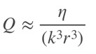
Where r is the radius of the smallest sphere enclosing the entire system, k = 2π/λ (free space wave number). Efficiency factor η can be approximately measured by comparison to a reference dipole. This rule is derived from near-field electric and magnetic storage, and refers to an ideal mathematical situation.
A short antenna has low radiation resistance and high reactance. This makes it hard to match to a transmitter or receiver, and even when matched the bandwidth is small. Over recent decades computer simulation allowed small designs to be optimised, as shown in this paper. No design has been proven to reach or exceed the Chu Limit. Perhaps they are looking in the wrong place?
“EH Antennas” disowned, but…
Before and since the EH antenna work, I read dozens of books and scientific papers, looking for ideas for small antennas. Those I looked at and may return to were…
Direct Antenna Modulation (DAM)
The Chu-Wheeler Q-factor limit is based on energy storage in the E and H near fields. If we disrupt the energy storage, the rules change. The bandwidth would be greatly increased, but the modulation would have to be digital and adapted to suit the antenna characteristics. Forget analog signal transmission, it would not work. Also the transmitter would be part of the antenna.
DAM was proven to work in a limited way. A more recent experiment (link to rare free document from the IEEE) does it differently. The document has several aspects of fresh thinking and some practical tests rather than reams of maths. Whilst not easily applied to ham radio, their research is not focussed on the narrow area of GHz mobile comms.
Spin Field Ferrite Rods
Ferrite rod AM antennas as found in cheap AM radios give good sensitivity but are also very small. Perhaps there is some anomaly there, and I am not the only one to think so. The spin field antenna from Graham Maynard (SK) goes against conventional theory and is described on his detailed web pages.
Graham’s insight is/was the textbook image of an electromagnetic wave being alternating E and H fields is wrong. The fields cannot be separated or combined in this way, as the EH antenna tests confirm. Those who constructed such antennas find they perform better, but not much better, than air-core loops. A more practically based document is here.
Despite a small community of medium-wave DX’ers using these, no experimental confirmation of Graham’s theory has been made. “Ultralight-DX group” (Groups.io) is completely disinterested in the basic physics. I don’t think Graham’s theory is correct, but have no evidence to back that up beyond the less than stellar result of these loops.
It would still be interesting to make a ferrite sleeve antenna from ferrite sheets, as used for 13.56MHz near-field communications devices (think Apple/Android pay). The sheets would make a lighter design, which doesn’t look like an explosive charge, as previous designs!
Stub matched “metamaterial” dipole
This was brought to my attention by stories about “metamaterial” a few years back. Arranging a shaped secondary element in the near field of a shortened dipole gives an effective matching system. The near fields of the dipole are loaded by the secondary element. Putting additional elements in the near-field can increase radiation resistance. Because a short antenna has low radiation resistance, the parasitic elements must be used to increase it to match a 50 ohm feed line.
There’s no metamaterial involved in this. Metamaterial is where hundreds of cells create negative refractive index. It’s useful when applied to microwave components, but at HF the resonant structures are impractically large. It’s nothing more than a new loading method. HF antennas are a different game to the UHF and SHF devices shown in theoretical papers.
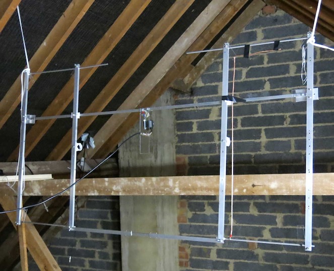
The resulting antenna is high-Q, narrow bandwidth as predicted by the Chu limit. It performs well down to ka=0.4, which represents a 1.4m long antenna at 28MHz. This is still a good result and a useful antenna design which received no interest at all from the amateur radio community. Local signal tests are within 2dB of a reference dipole. On skywave transmissions it is difficult to tell them apart. Rotating the prototype in the horizontal plane shows a radiation pattern very similar to a dipole. Photo of prototype strung up in the loft.
The stub match technique is an obvious pairing with the next concept.
Non-Foster Matching
Non-Foster is a holy grail of antenna design. Foster’s reactance theorem states passive components never have negative reactance. But it can be can be created using active devices. Applied to antennas, the loading inductor or passive matching circuit is eliminated. This defeats both the energy storage limitation of Chu-Wheeler and the need for unreliable mechanical variable inductors and capacitors.
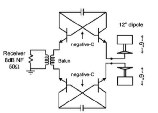
There is a general limit on the bandwidth over which a good impedance match can be obtained in the case of a complex load impedance. It relates to the ratio of reactance to resistance, bandwidth over which we want to match, lowest SWR expectations, and is called the Bode-Fano limit. The basic principle of a negative impedance converter (NIC), is summarised by this fragment of circuit diagram. A floating and balanced feed from a dipole:
Removal of energy storage elements (passive components) results in an efficient broadband antenna. It has already been demonstrated in broadband receiving applications. Transmitting is more complicated, but the solution is to have the transmitter output stage as part of the antenna itself. Such technology would be revolutionary in MF/HF communications, where the limitation of antenna performance at low frequency outweighs any improvements possible in receivers or transmitters.
Non-Foster matching would be a paradigm shift, BUT implementing it and even understanding intricacies of the theory are difficult. Stability is the main problem. Simulation only gets so far because objects near the antenna cause its equivalent circuit to shift, introducing a high probability of oscillation. Implementing fixed station systems would seem to be easier than handheld or mobile for this reason.
The lower (HF) frequencies must be easier to implement than UHF/SHF. Equipment based on this technology may never happen if amateurs don’t do research for themselves. There are no commercially sold equipments using non-Foster matching, a wide open field for amateurs to break new ground if we can only make it work!
Crossed Field Loop & Maurice Hately
Some words about the crossed field loop (CFL). This was the successor to the crossed field antenna developed by Prof. Maurice Hately (GM3HAT) with great fanfare and controversy in 1989. The CFL dates from the late 1990s, and has US patent US6025813. I built one to the design as closely as I could, with this result:
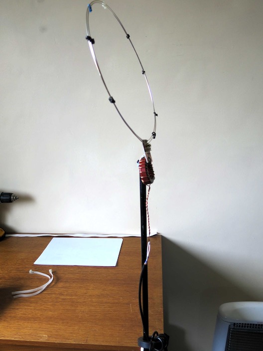
Only some cheap parts are used, thick copper wire, a T200 iron dust toroid and two small trimmer capacitors. Performance was >10dB down on a conventional wire antenna, and bandwidth very narrow. This barely merits the word "antenna," it's almost a non-radiating narrow band dummy load. It performs even worse than the EH antenna.
I found it was easy to control common mode current, by moving the coil tap to the centre, and using two turns of the coax thru a clip-over ferrite. Common mode current was always used by opponents of this design to explain its mode of operation. I have a different opinion, and also may explain why Prof. Hately vigorously defended his antenna until his death in 2012.
Any tuned circuit will radiate a small amount, and give an SWR dip when viewed on a network analyser. I think Prof. Hately was deceived by a combination of “anything works“ and the vagaries of HF propagation. Antenna testing can be VERY MISLEADING.
Updated 20191031
The subject of antennas is arcane and boring to the crowd. But to anyone trying to talk (or type) to the world from a small plot in crowded England, they’re an interesting headache. This is what got me into the subject.
A good HF antenna has:
1. High efficiency
2. Small size in any dimension
3. Good bandwidth (or easy to tune)
4. Practical to build and mechanically robust
The issue of directional antennas (e.g., Yagi) is left aside, as it’s something of a separate problem.
An antenna system is electrically small if it's enclosing sphere is <λ/2π. So, a 10m band antenna under 1.6m long qualifies, for instance. This is the definition of a small antenna from 60 years ago, established by the Chu-Harrington limit. It defines the minimum Q factor (or maximum bandwidth) a certain size of antenna can achieve, with linear polarisation and 100% efficiency:
Where r is the radius of the smallest sphere enclosing the entire system, k = 2π/λ (free space wave number). Efficiency factor η can be approximately measured by comparison to a reference dipole. This rule is derived from near-field electric and magnetic storage, and refers to an ideal mathematical situation.
A short antenna has low radiation resistance and high reactance. This makes it hard to match to a transmitter or receiver, and even when matched the bandwidth is small. Over recent decades computer simulation allowed small designs to be optimised, as shown in this paper. No design has been proven to reach or exceed the Chu Limit. Perhaps they are looking in the wrong place?
“EH Antennas” disowned, but…
Before and since the EH antenna work, I read dozens of books and scientific papers, looking for ideas for small antennas. Those I looked at and may return to were…
- Line loading
- Dielectric resonators
- Small magnetic loops
- Spin field ferrite rods
- Direct Antenna Modulation
- Metamaterial antennas
- Non-Foster matching
- Crossed-field loop revisited
Direct Antenna Modulation (DAM)
The Chu-Wheeler Q-factor limit is based on energy storage in the E and H near fields. If we disrupt the energy storage, the rules change. The bandwidth would be greatly increased, but the modulation would have to be digital and adapted to suit the antenna characteristics. Forget analog signal transmission, it would not work. Also the transmitter would be part of the antenna.
DAM was proven to work in a limited way. A more recent experiment (link to rare free document from the IEEE) does it differently. The document has several aspects of fresh thinking and some practical tests rather than reams of maths. Whilst not easily applied to ham radio, their research is not focussed on the narrow area of GHz mobile comms.
Spin Field Ferrite Rods
Ferrite rod AM antennas as found in cheap AM radios give good sensitivity but are also very small. Perhaps there is some anomaly there, and I am not the only one to think so. The spin field antenna from Graham Maynard (SK) goes against conventional theory and is described on his detailed web pages.
Graham’s insight is/was the textbook image of an electromagnetic wave being alternating E and H fields is wrong. The fields cannot be separated or combined in this way, as the EH antenna tests confirm. Those who constructed such antennas find they perform better, but not much better, than air-core loops. A more practically based document is here.
Despite a small community of medium-wave DX’ers using these, no experimental confirmation of Graham’s theory has been made. “Ultralight-DX group” (Groups.io) is completely disinterested in the basic physics. I don’t think Graham’s theory is correct, but have no evidence to back that up beyond the less than stellar result of these loops.
It would still be interesting to make a ferrite sleeve antenna from ferrite sheets, as used for 13.56MHz near-field communications devices (think Apple/Android pay). The sheets would make a lighter design, which doesn’t look like an explosive charge, as previous designs!
Stub matched “metamaterial” dipole
This was brought to my attention by stories about “metamaterial” a few years back. Arranging a shaped secondary element in the near field of a shortened dipole gives an effective matching system. The near fields of the dipole are loaded by the secondary element. Putting additional elements in the near-field can increase radiation resistance. Because a short antenna has low radiation resistance, the parasitic elements must be used to increase it to match a 50 ohm feed line.
There’s no metamaterial involved in this. Metamaterial is where hundreds of cells create negative refractive index. It’s useful when applied to microwave components, but at HF the resonant structures are impractically large. It’s nothing more than a new loading method. HF antennas are a different game to the UHF and SHF devices shown in theoretical papers.
The resulting antenna is high-Q, narrow bandwidth as predicted by the Chu limit. It performs well down to ka=0.4, which represents a 1.4m long antenna at 28MHz. This is still a good result and a useful antenna design which received no interest at all from the amateur radio community. Local signal tests are within 2dB of a reference dipole. On skywave transmissions it is difficult to tell them apart. Rotating the prototype in the horizontal plane shows a radiation pattern very similar to a dipole. Photo of prototype strung up in the loft.
The stub match technique is an obvious pairing with the next concept.
Non-Foster Matching
Non-Foster is a holy grail of antenna design. Foster’s reactance theorem states passive components never have negative reactance. But it can be can be created using active devices. Applied to antennas, the loading inductor or passive matching circuit is eliminated. This defeats both the energy storage limitation of Chu-Wheeler and the need for unreliable mechanical variable inductors and capacitors.
There is a general limit on the bandwidth over which a good impedance match can be obtained in the case of a complex load impedance. It relates to the ratio of reactance to resistance, bandwidth over which we want to match, lowest SWR expectations, and is called the Bode-Fano limit. The basic principle of a negative impedance converter (NIC), is summarised by this fragment of circuit diagram. A floating and balanced feed from a dipole:
Removal of energy storage elements (passive components) results in an efficient broadband antenna. It has already been demonstrated in broadband receiving applications. Transmitting is more complicated, but the solution is to have the transmitter output stage as part of the antenna itself. Such technology would be revolutionary in MF/HF communications, where the limitation of antenna performance at low frequency outweighs any improvements possible in receivers or transmitters.
Non-Foster matching would be a paradigm shift, BUT implementing it and even understanding intricacies of the theory are difficult. Stability is the main problem. Simulation only gets so far because objects near the antenna cause its equivalent circuit to shift, introducing a high probability of oscillation. Implementing fixed station systems would seem to be easier than handheld or mobile for this reason.
The lower (HF) frequencies must be easier to implement than UHF/SHF. Equipment based on this technology may never happen if amateurs don’t do research for themselves. There are no commercially sold equipments using non-Foster matching, a wide open field for amateurs to break new ground if we can only make it work!
Crossed Field Loop & Maurice Hately
Some words about the crossed field loop (CFL). This was the successor to the crossed field antenna developed by Prof. Maurice Hately (GM3HAT) with great fanfare and controversy in 1989. The CFL dates from the late 1990s, and has US patent US6025813. I built one to the design as closely as I could, with this result:
Only some cheap parts are used, thick copper wire, a T200 iron dust toroid and two small trimmer capacitors. Performance was >10dB down on a conventional wire antenna, and bandwidth very narrow. This barely merits the word "antenna," it's almost a non-radiating narrow band dummy load. It performs even worse than the EH antenna.
I found it was easy to control common mode current, by moving the coil tap to the centre, and using two turns of the coax thru a clip-over ferrite. Common mode current was always used by opponents of this design to explain its mode of operation. I have a different opinion, and also may explain why Prof. Hately vigorously defended his antenna until his death in 2012.
Any tuned circuit will radiate a small amount, and give an SWR dip when viewed on a network analyser. I think Prof. Hately was deceived by a combination of “anything works“ and the vagaries of HF propagation. Antenna testing can be VERY MISLEADING.