Updated 20230130
This page gives background information to the “End-connected Windom” antenna article published in Radcom, December 2017, and general comments on this type of antenna.
The windom dates back to the 1920s and has a long history… but Loren Windom didn’t invent it, see here for a longer history document. After testing several types of wire antennas I concluded this one is best. If you have room (and permission) for a tower and beam, then well and good. But even a Hexbeam (which is probably the best small wire beam) only covers 20m and upwards. Unfortunately there are few modern windom designs available commercially. There’s wrong information in books and on the web telling people to use 1/3 split and incorrect transformers - a path to failure!
The windom if correctly made and adjusted performs equally well as any other wire antenna, and offers better multi-band performance than any other. I’m not the only one who thinks that!
The end-connected design has been tested at various lengths up to a 40m long version covering 80m. Used as an inverted-L and (the 10m long version) vertical it also gives a good account itself. If your property as at one end of your plot, this antenna is undoubtedly the best design currently available to cover many bands with 1 piece of wire. It makes me rather angry to see people struggling with G5RVs, feeders strung across their garden, and expensive tuners, when this design is far less obtrusive and a lot cheaper.
End-connected windom comments
Q: Why is it called “windom” when “off centre fed dipole” is a more accurate description?
A: Loren Windom’s name is well known in association with the antenna, and gives it something of an identifiable brand. Lots of variants have the tag “G5RV," so why not Windom?
Q: Why is it not called end-fed?
A: The actual feed-point is in the middle despite the physical connection appearing to be at the end. Therefore end-connected is a more accurate description (thanks to G3UNA)
Q: Did you get the idea from the Russian City Windom?
A: Yes, but my design has differences in the split-point and balun construction
Q: Can I buy the antennas commercially?
A: Yes, sort of. The City Windom sold by Wimo antennas is similar but covers less bands, and is also distributed in the UK by RadioWorld and Lamco/Vine Antennas. Making your own will be much cheaper than paying two middlemen…
Q: I made one and found the SWR is very high
A: The lengths given in the article are a starting point, it will need to be cut back. Tuning this type of antenna is much easier with a network/antenna analyser, basically impossible with a basic SWR meter. Also remember the velocity factor for different wire types varies.
Q: Why is the windom sightly longer than a half wave?
A: Due to the imbalance, the capacitance between the antenna and ground at the ends is less than a dipole, so raising the frequency. See RadCom April 2015 article
Q: Can it be modified to work on other/more bands?
A: Yes. That’s an open question with more than one answer!
Q: These antennas are lossy and work as well as a piece of damp string.
A: No, if you construct it properly the losses are <0.5dB compared to a single band dipole. So small it will make no difference on the air, and compare the inverted-V results at the bottom of this page
Q: The ARRL Handbook says William Everitt invented it, not Windom?
A: The ARRL is incorrect, see here for a longer history document. Also see letter from Brian Austin (G0GSF) in June 2015 RadCom, page 97
Q: It suffers badly from common mode current and is noisy
A: No not if the transformers are made correctly.
Q: Can it be used as a vertical, or inverted “L”?
A: Yes, myself and several others have done that
Q: The ARRL handbook recommends using twin feeder and a tuner
A: The ARRL handbook and their antenna handbook are 40+ years out of date! The twin feeder version can be considered obsolete for many reasons. The number of bands covered depends on how much space you have. For more bands, consider the “807” which covers 7 bands from 80m upwards, hence its name
Q: Where can I find more information?
A: Look here, for thousands of posts and ideas for different designs, all information is public domain (Groups.IO login required)
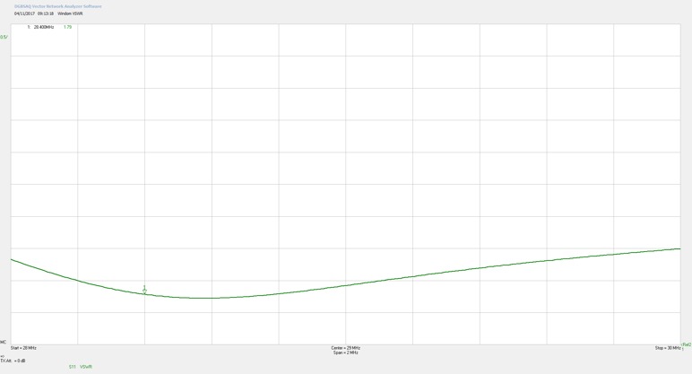
VSWR Plots
The full band response:
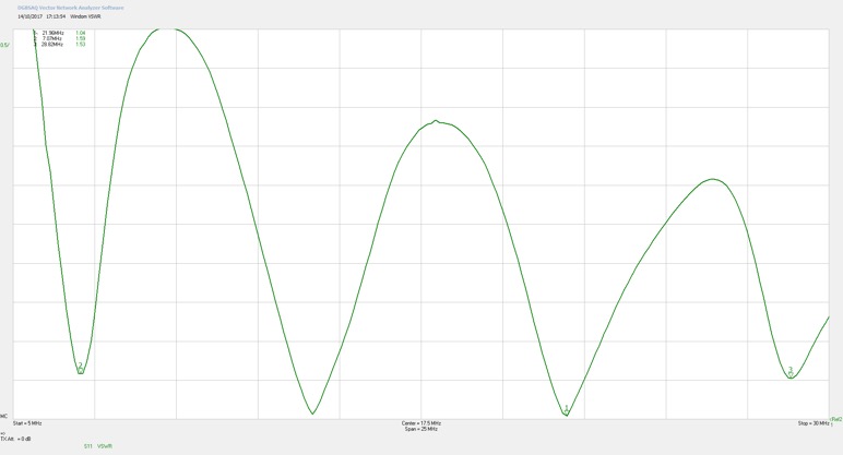
On 40m:
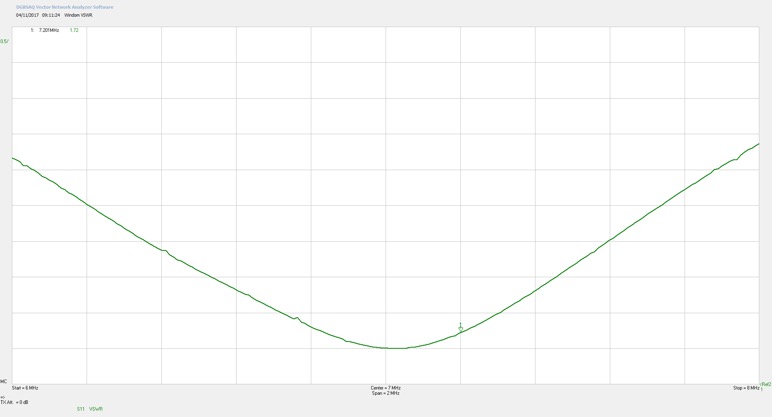
On 20m:
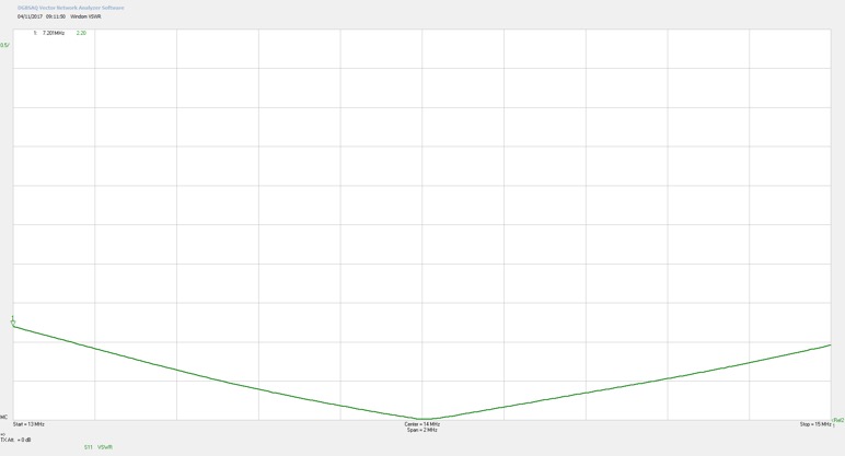
On 15m:
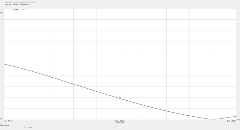
On 10m:
Further Notes
The first EC-windom was constructed in 2014 and it performed well for 3 years. However, since negotiating with my neighbours the antenna presently in use here is an 807 inverted-V, which is also an off centre fed design. It covers 80m and 17m in addition to the 4 bands of the one shown in the Radcom article.
I compared the 20m long windom with a traditional inverted-V.
1. Inverted-V 35m total length, fed with open wire feeder with remote ATU
2. End-connected windom, 20m long, no tuner, running across the inv-V at approximately right angles.
160m: winner inv-V
Inv-V 1’S’ lower noise
Inv-V 2 ’S’ higher signal
80m: winner inv-V
Noise level equal
2 ’S’ points more on inv-V
40m: winner inv-V (just)
2 ’S’ point lower noise on V
1 ’S’ point higher signal on windom
30m: no winner
Neck & neck on Rx, but windom has high SWR, cannot Tx
20m: no winner
2 ’S’ point lower noise on V
1 ’S’ point higher signal on windom
15m: winner windom
Noise 2 ’S’ higher on windom
Signals 2 'S' higher on windom
10m: winner windom
Noise and signals +2 ’S’ on windom
The inverted-V is 15m longer and further away from the house. It has a £400 remote antenna tuner, and the open wire feeder looks ugly. The windom is much easier to setup, needs only 2 supports, no expensive tuner, takes up less room.
Conclusion: For the money the windom wins, but with the amount of wire in the air the inverted-V was bound to be better on LF. The windom was closer to the house and mains wiring, hence higher noise.