Updated 20170930
As much of my work is empirical testing, sources of error are important. On this page I show some of the test equipment used for measurements on the other pages. Comparing antennas is more difficult than you expect. There are many variables such as:
- Near field effects, measurements should be in far field
- Far field zone is many metres away for HF antennas
- Signal resolution of the measuring receiver (ideally 0.1dB)
- Frequency dependency of the receiver itself and its antenna
- Polarisation effects
- Effects of weather conditions, moisture on Rx or Tx antenna
- Propagation changing over time
- Ground effects
- Directional effects (azimuth plane)
- Background noise/signals adding to received amplitude
- Variations in transmitter output from temperature
- Moving objects close to the receiver or transmitter antenna
- SWR mismatch as either antenna is adjusted
- Effects of the above on any reference antenna when compared to the AUT (antenna under test)
- Take-off angle (elevation plane)
- Losses of common mode current chokes
For peer reviewed science, calibrated test equipment would be necessary. So my results definitely do not reach “five sigma” certainty!
A far field receiver with accurate relative signal readings, plus instant feedback to the transmitter solves several measurement problems. It allows instant results from adjustments. Points 1,2,3,5,6,7,9,10,13 can be eliminated or compensated for with this method. For example, near immediate comparisons of adjustments basically eliminates changes in propagation which happen quite slowly. Also, background signals (10) can be avoided by moving a few kHz.
I have a transmitter with a test antenna, and an online receiver a few miles away. The transmitter antenna being the one under test and adjusted. The online receiver used was the KiwiSDR.
The major factors not solved by the VNA and online receiver are points 5,9,11,13,14. Polarisation can be addressed by a rotatable receive antenna. Variations in Tx power can be monitored by a power meter. Take-off angle at a particular test site is impossible to control, but influenced by height and grounding, which if kept constant give a reliable comparison.
All that can be done to reduce objects near either antenna is to site the Rx one where it is less likely to be disturbed. For the Tx, large objects near the antenna (e.g. bodies, ladders) should be moved away or into the same position during successive tests. The effect of such objects can be seen immediately by readings of the online receiver and eliminated.
Azimuth directionality is probably not a big uncertainty, because small antennas are inherently omni-directional, “non-beam” by nature.
Where comparative signal plots are shown on this page, they were taken within an hour of each other except where noted. This measure, in addition to testing in dry conditions only, mitigates any propagation influences. Testing was done outside winter months and not during any major sporadic-E events. The receiving antenna was not substantially altered during the test period.
If you think my attempts at reducing measurement errors are insufficient, be free to add 3dB uncertainty to most numbers on this page. With my openness of showing the test equipment used, perhaps some objection to these results can be dispelled.
Antennas at receive side
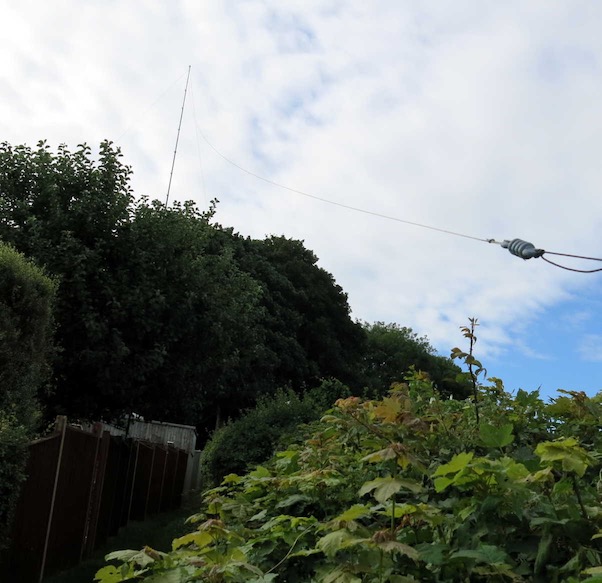
Frequency used approximately (+/- QRM) 28MHz. Inverted-V dipole, total length 35m, 11m high at centre, approx 1m high at ends. Situated at edge of open arable field. Photo follows.
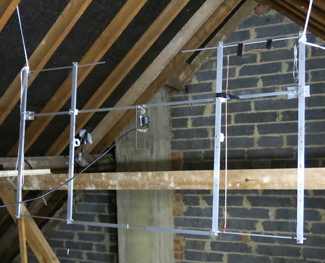
“Meta-material” mini-dipole. Situated in loft at same site as the inverted-V. Length 1.5m, width 0.75m. Efficiency similar to standard dipole, but narrow bandwidth. Small size makes it easy to rotate for polarisation testing.
Transmitter test site
The transmitter site is on a slate tile roof.
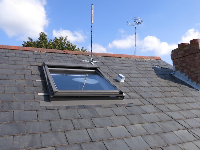
The roof window allows easy access to modify antennas, and the KiwiSDR provides instant signal readings from 3 miles away thru the Internet.
Polarisation testing
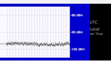
An experimental antenna was tested using the KiwiSDR S-meter extension for vertical polarisation using the mini-dipole.
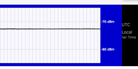
Then for horizontal. 96dBm - 72dBm = 24dB, so this antenna is strongly vertically polarised.
Mobile antenna testing
A modified EH antenna was constructed for mobile use. In this photo the small antenna is on the MINI car roof, and the size of the reference antenna is obvious.
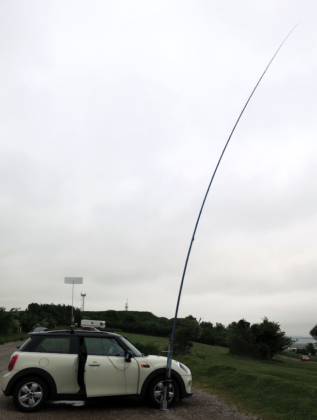
To a local station 3 miles away on 14.250MHz, these signal measurements were obtained:
Windom vertical = S8.5 (26dB) to hex beam and S7.5 (22dB) to vertical receive antenna
Small antenna = S9+1dB (28dB) to hex beam and S6 (20dB) to vertical receive antenna
In other words the small antenna is a match for the large one, although the bandwidth is narrower. In A/B switched tests I preferred the small antenna on receive via sky wave propagation. With the local station transmitting it was noted the signal strength on receive between the 2 antennas was indistinguishable on the Elecraft KX3 signal bar-graph.
Another station was set-up at a beach, with a 20m long 4-band windom and the small mobile antenna. Over several hours signal strengths on 20m were compared directly. It was found the background noise and signal readings on an Elecraft KX3 were equal or above the long wire antenna. Some videos were made and put on YouTube here and HERE and HERE.
Then a helically wound mobile whip was compared. The two antennas operating on 14.250MHz a few minutes after the first test.
Small antenna = S9+3dB (32dB) to hex beam and S6 (18dB) to vertical receive antenna
Helical whip = S9+2dB (31dB) to hex beam and S6 (18dB) to vertical receive antenna
This result shows how effective the car body is at reducing ground losses, with the AmPro whip coming out slightly better than the full length vertical. It should be noted the whip is 2.5m (0.12λ) vs. the small antenna of 1.m (0.05λ). A length reduction of 2.3x by conventional means could be achieved by a capacitive top loading system. The top loading would be more mechanically unwieldy and probably result in impedance changes, necessitating a matching network.
The result of these tests is the warning ANTENNA TESTING CAN BE VERY MISLEADING.
The modified EH antenna is slightly better than the large half-wave or the AmPro whip. This is inconsistent with my statement the EH is 7-10dB down on a conventional antenna.