Updated 20191230
Tests for 2019-20
An attempt to prove combined electric TE10 and magnetic TM10 mode charge acceleration and hence radiation is possible. The antenna works well on 10m with a 350kHz 2:1 SWR bandwidth. The bandwidth is about 3x a standard small transmitting loop of 0.35m diameter. The antenna is 0.75m tall and tests against a reference antenna will happen sometime. I always thought it ridiculous that a conventional small magnetic loop antenna has such a lot of stored energy in the tuning capacitor. If a way could be found to release some of this stored energy, a much wider bandwidth could be realised.
I have a 10m prototype using a PCB-inductor.
2018
A 160m band prototype was successful with 10-12dB better signals than my 40m long windom. This doesn’t “prove” anything scientifically but gives a useful top-band antenna at just 7m tall. The antenna can be compared to my 807 Windom with the online HDARC KiwiSDR. Use the antenna switch extension. A lot more background work happened during 2018, but I’m keeping some developments private…
2017 - Conventional loaded antenna comparison
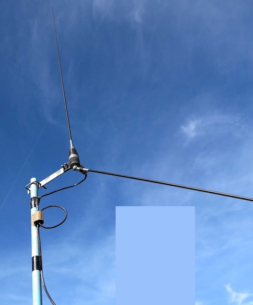
For a frequency near 28MHz, a Boomerang 27W was mounted in the same position, just slightly higher to accommodate its long bottom dipole element. The boomerang is 1.75m x2 = 3.5m long, which is 0.67 of a half wave dipole. It was compared with horizontal, tilted and vertical polarisation to a rebuilt capacitive antenna of 0.7m height. The MMI-dipole used for horizontal and vertical, the inverted-V for tilted polarisation.
Boomerang signal readings off KiwiSDR:
Horizontal = -86dBm
Tilted = -74dBm
Vertical = -75dBm
Capacitive signal readings off KiwiSDR:
Horizontal = -96dBm
Tilted = -75dBm
Vertical = -72dBm
EH antenna signal readings off KiwiSDR:
Horizontal = -96dBm
Tilted = -80dBm
Vertical = -80dBm
It’s difficult to “average” these results because they’re absolute values in dBm, but it’s clear the Capacitive is very close to the Boomerang. Taking half the Boomerang length as a fair comparison, it’s 1.75/0.7 = 2.5x longer than the Capacitive antenna. As said on the previous page, you should assume some uncertainty in these measurements. Boomerang photo…
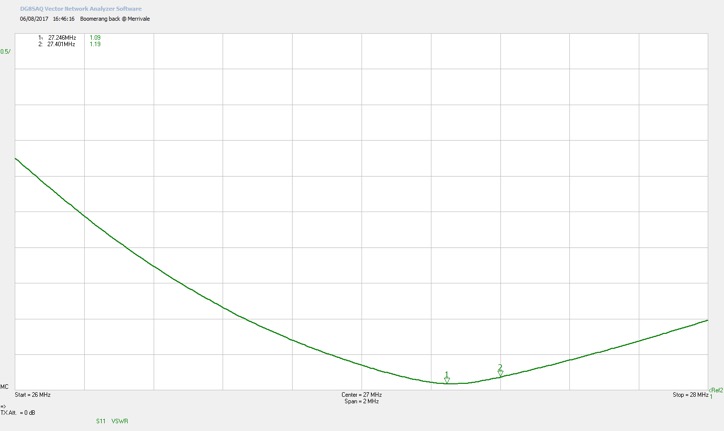
Bandwidth of Boomerang 27W, 2:1 = 1.2MHz.
Bandwidth of capacitive antenna, 2:1 = 600kHz, albeit centre frequency 500kHz higher.
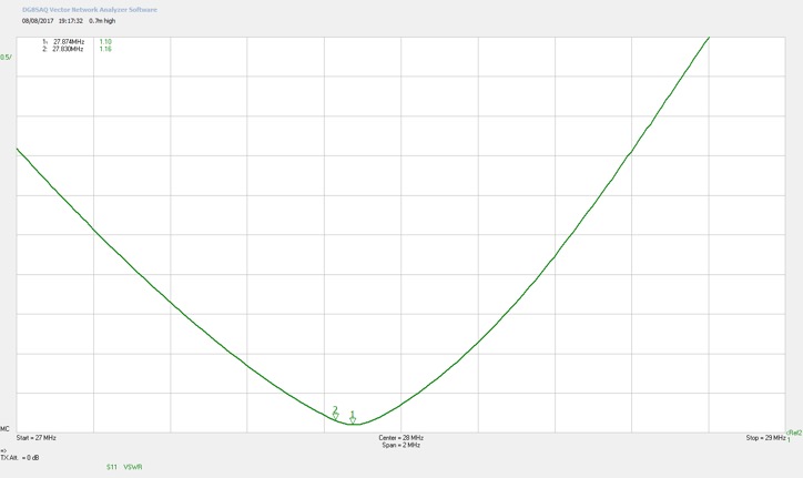
Exactly half the bandwidth.
Chu-Wheeler Limit Comparison
Any suggestion a short radiator can match a far longer one is controversial. Does it contravene the Chu-Wheeler criterion? It measures as strongly vertically polarised, so the standard Chu-Wheeler formula applies.
Radian-sphere 0.75 high, 0.4 wide = 0.84m (by Pythagoras)
Frequency = 28MHz
ka = 2xPI/λ x 0.84 = 0.50
Efficiency (eta η) estimated by measurement at 0.5 (-3.0dB down on half-wave vertical)
There are several documents transposing the basic Chu formula to give VSWR bandwidth, here is a link to one. Prof. S.R. Best gives equation (6) with a handy calculation including SWR (s). Working out on paper gives 0.28MHz. Measured 2:1 SWR bandwidth = 0.6MHz, so about twice the conventional theory. The document also gives bandwidth comparisons for many proven small antenna designs.
Of course this doesn't include the size of the ground-grid (or ground plane). The grid may not be acting purely as a reflector. If anyone likes to correct my arithmetic above, go ahead. With all uncertainties involved, I cannot confirm the antenna breaks conventional theory. But it’s definitely a good antenna for its size.
H-Field Probe Test
H-field probe test… is there a magnetic field between the 2 plates? To get some idea, I made a simple H-field probe. Consisting of a shielded loop, diode detector, and moving coil meter. The coax braid stops the electric field, but the magnetic field penetrates the braid. Shielding is important to minimise pickup from the strong high voltage electric field present in antenna testing.
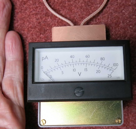
Showing the results on paper is difficult. The largest magnetic field seems to be the side of the grid over the edge of the ground-grid. The side near the middle of the ground-grid has hardly any magnetic reading. The field drops off away from the plates and there is no magnetic component between them, Stating the obvious to any electrical engineer that electro-magnetism only occurs in the vicinity of conductors.
This experiment disproves what some say about displacement current between two plates of a capacitor, caused by an electric field. A magnetic field can only be made by current flow in wires. As you can see I measure no magnetic field when the meter is moved away from the plates. This is shown mathematically by Jefimenko’s equation.
The H-field probe proves the cube-distance law of magnetism, and that there is no “duality” in free space between magnetic and electric fields.